
Velocity Map Imaging
| Chemical Dynamics Home |
| News |
| Research Themes |
| Research Methods |
| VMI |
| LIF |
| MB |
| CMB |
| FMS |
| ToF |
| People |
| Jobs |
| Links |
| |
Last updated February 2026 |
VMIThe velocity map imaging (VMI) method allows us to take a picture of the velocities, i.e. speed and direction, of the products of dynamical processes such as photodissociation and bimolecular collisions. VMI is an adaptation of time of flight mass spectrometry (ToFMS), and as such also has the ability to separate, and selectively detect, ions by mass. In our experiments such ions have usually been formed by the quantum state selective Resonance Enhanced Multi Photon Ionisation (REMPI) method. We use REMPI-VMI as a detection technique in a wide variety of our experimental projects to give us a simultaneous measurement of the internal energy & velocity of reaction products. A decade after the development of ion imaging by Chandler & Houston1 (the addition of 2d imaging capability to a standard ToF apparatus with homogeneous fields) Eppink and Parker introduced the Velocity-Map Imaging technique.2 They removed the grid electrodes, replacing them with circular ring electrodes. The simplest velocity-mapping design requires 3 electrodes, and the resulting electric field structure is inhomogeneous. The first advantage over the Wiley-Maclaren design is the removal of the distortions and transmission losses arising from the grid electrodes. However, much more importantly, it also introduces mapping of the velocity of the ions to different locations on the detector, independent of their initial positions. This is a result of the shape of the inhomogeneous fields, which form an Einzel lens. This provides both a direct measure of the desired property, and one that is of much higher resolution (a factor of 20 improvement over ion imaging in Eppink and Parkers initial apparatus). Even better performance can be achieved with more sophisticated ion-optic designs, particularly by separating the acceleration and focussing stages. 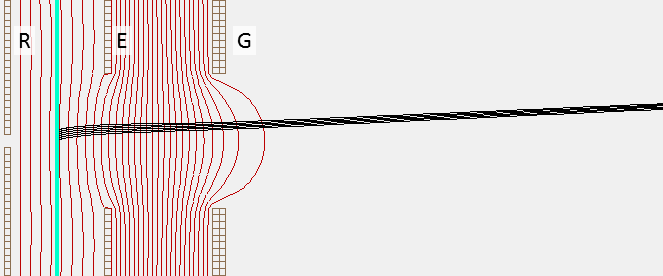
|
|