
CD3 Radical Scattering
The dynamics of the inelastic collisions of CD3 radicals with a range of atomic and molecular colliders is studied using the crossed molecular beams technique combined with velocity map imaging.
|
|
|

|
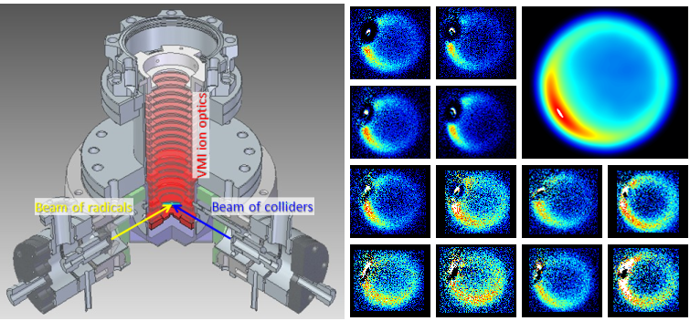
Left: A schematic of the crossed molecular beams apparatus, the shade of red on the ion optics indicates the strength of the electric field. Right: Raw images of the scattering of CD3 with He, including (top right) the instrument function as calculated by a Monte Carlo simulation of the experiment. |
Rotational energy transfer through inelastic collisions
These experiments used a compact crossed molecular beam velocity map ion imaging system to study the dynamics of inelastic collisions of radicals with a selection of atomic and molecular collision partners. The experiments consists of a primary molecular beam of jet-cooled radicals (such as CD3 or CH3) and a secondary beam of various colliders (Ar, He, D2, H2 and N2) which are crossed at 90° in a high vacuum chamber, and the velocities of the scattered radicals were velocity map imaged following resonsnce enhanced multiphoton ionization (REMPI) with rotational level resolution.
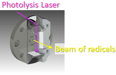 Molecular beams are formed by supersonic expansion of gas samples through a pair of pulsed valves and the expansions are collimated by skimmers. The primary molecular beam is formed by a modified solenoid valve with a pair of prisms mounted on the face plate allowing for the coupling of a photolysis laser which induces fission of a seeded precursor molecule beam (CD3I or CH3I) leading to the formation of a cooled molecular beam of CD3 or CH3 radicals. The beam of colliders is formed by a second solenoid valve. The advantage of the compact crossed molecular beam machine is the small distance from the nozzles to the scattering region, which results in a larger density of particles in the interaction region.
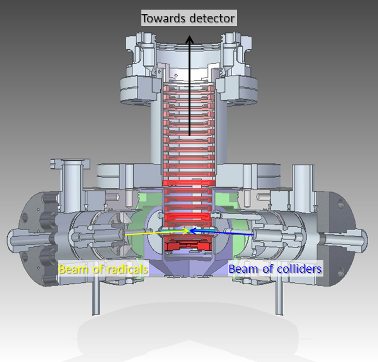 The point of intersection of the two molecular beams is located between a vertically mounted stack of electrodes forming an ion optics assembly for velocity map imaging. Scattered radicals are ionised by a tuneable probe dye laser accessing a rotationally specific REMPI transition. Ionised radicals are then accelerated by the electric field created by the ion optics projecting the ions upwards towards a position sensitive velocity map-imaging detector.
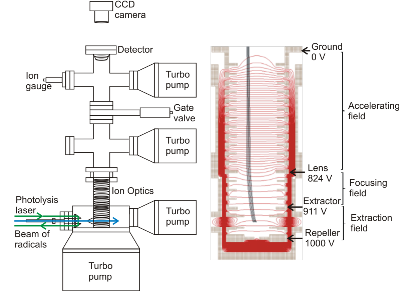 The design of the ion optics for DC slice imaging. The red lines represent the electric field lines of force created by electrodes with shown applied voltages
The ion optics are calibrated to perform sliced velocity map imaging and consists of 20 electrodes forming three sections of homogeneous electrostatic field; an extraction field (consisting of 3 electrodes), a focusing field (consisting of 4 electrodes) and an accelerating field (consisting of 13 electrodes). The electrodes forming the homogeneous acceleration field stretches the ion packets along the flight axis according to the initial velocities of the neutral radicals. A short (30 ns) voltage pulse at the MCPs then allowed only a thin centre slice of the ion packet to be recorded, corresponding to radicals scattered within, or close to the plane of the crossed molecular beams. Direct analysis of the slice image gives a three dimensional velocity distributions of the inelastically scattered radicals without need for image reconstruction techniques.
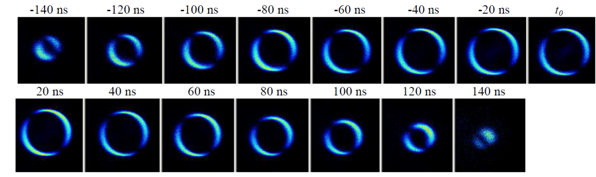 Time-sliced images of I from CH3I photodissociation at 286.705 nm. The time of slicing is shown with respect to the arrival time (t0) of the centre of the Newton sphere. The detector gate width was set to 20 ns.
The physical quantity measured in these crossed molecular beam experiments for inelastic scattering processes is the angular distribution after the collision, the distribution of particles scattered into a solid scattering angle, from this the differential cross section for the inelastic scattering process can be obtained. In general the DCS is defined as the ratio of the scattered flux of particles (number of particles per unit time) per unit solid angle to the incident flux per unit area. The DCS is a powerful tool for describing the dynamics of inelastic collisions. A forward peaking DCS (scattering into small angles) indicates glancing collisions occurring at large impact parameters, while a backward peaking DCS (scattering into large angles) corresponds to head-on collisions, which tend to be associated with small impact parameters. To obtain a DCS for a particular inelastic scattered radical experiment a suitable density-to-flux conversion needs to be taken into account. The density-to-flux conversion removes the contribution of the centre of mass velocity in lab frame providing an image of the radicals that is only dependent on the radical’s velocity relative to the centre of mass (removing the asymmetrically biased due to the radicals that are fast or slow in the lab frame).
-
Rotationally inelastic scattering of CD3 and CH3 with He: comparison of velocity map-imaging data with quantum scattering calculations
Chemical Science 4 4199–4211 (2013)
doi: 10.1039/C3SC52002A

-
Differential and integral cross sections for the rotationally inelastic scattering of methyl radicals with H2 and D2.
J. Chem. Phys. 140 204318 (2014)
doi: 10.1063/1.4879618